Know-how for Temperature Measurement
 Temperature
Temperature
Countermeasure for Noise Exacerbation in Multi-point Measurement of Temperature / Noise Elimination Using a Common Potential
When measuring temperatures at multiple points with a single measuring instrument, noise may appear in the output due to the potential difference between each measuring points. Noise can be eliminated by short-circuiting the negative terminal of each channel’s thermocouple to the same potential.
(When the potentials of the measuring points are different and short-circuiting produces a large flow of current, it would be very dangerous. Please check the insulation of the thermocouples, as well as the potential and charge of the measuring points in advance before short-circuiting.)
How to Enhance Antistatic Measures (WM2000TA/TB)
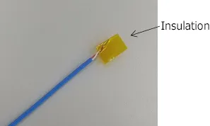
Insulating Thermocouples
Thermocouples are made of metal and are conductive materials. There are several ways to insulate the tip of the thermocouple to prevent static electricity.
For example, a sheathed thermocouple is generally insulated on the external metal and the thermocouple. When using a thermocouple with the tip exposed, simply insulate it with polyimide tape or the like before making contact with it to increase its resistance to static electricity, ensuring safe use.
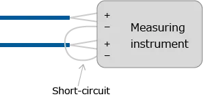
Negative Terminal Commonization
When a single measuring instrument is used to measure temperatures at multiple points, static electricity stored at each measuring point may be captured by the instrument to destroy the instrument itself. To prevent static electricity between measuring points from being captured by the instrument, the negative terminal connecting the thermocouples can be short-circuited to increase static electricity resistance.
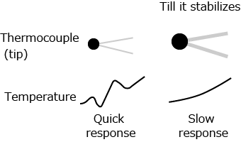
Tips for Temperature Measurement Regarding Thermocouple Thickness (Thermal Time Constant) and Contact Method
The measurement point is the tip of the thermocouple (where the positive and negative wires are connected).
The thicker the tip of the thermocouple, the longer it takes to warm up, resulting in a slower response (i.e. larger thermal time constant).
Differences in Measurement Results due to Differences in Response
- If the thermocouple is thin, the thermal time constant at the tip will be small, exhibiting high followability of temperature change. However, it faces disadvantages such that it is susceptible to breaks, vulnerable to noise, and may have high resistance value.
- If the thermocouple is thick, the thermal time constant at the tip becomes larger, worsening the followability to temperature change. Although there are disadvantages such as stiff wiring, slow response, and heaviness, the thermocouple is durable, making it possible to obtain stable measurement results since instantaneous temperature fluctuations are not visible.
In the case of temperature measurement using a thermocouple, as shown in the figure on the right, the tip of the thermocouple is in contact with both the object and the air.
When the object is heated, the temperature of the object and the temperature of the air are different.
The temperature at the tip of the thermocouple that becomes the measurement value is determined by the ease of transmitting the heat in each direction.
Ease of transmitting the heat is determined by thermal resistance and thermal capacity.
In general, thermal conductivity in solids and liquids >> thermal conductivity in gases; however, the amount of error varies depending on the thickness and shape of the thermocouple.
The following are some countermeasures against this issue:
- Use a thermocouple for surface temperature
- Use a thermocouple with low thermal capacity (thin)
- Embed the thermocouple
- Cover the thermocouple with tape or adhesive
There are two types of thermal conductivity to the air: thermal conduction by convection and radiation heat by electromagnetic waves.
When covering the tip of the thermocouple, it is recommended to use one with an emission level close to that of the object to be measured. (It is sufficient to use either metal or resin.)
When heat transfer to air is enhanced by creating strong airflow or by other means, thermal conductivity in solids or liquids may be smaller than the thermal conductivity in gases.
A typical example is cooling using fans and heat sinks.


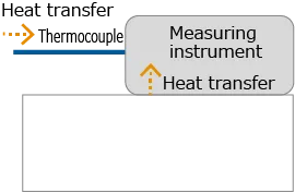
Principles of Thermocouple Measurement
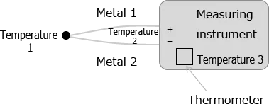
A thermocouple is composed of two different metals. When these two metals are connected, the temperature difference between their two ends generates a thermoelectromotive force.
The temperature of the contact point can be measured using a thermocouple and a thermometer.
The configuration of the measuring instrument is shown in the figure on the right.
Temperature difference between the two ends of the thermocouple = Temperature 1 – Temperature 2
The voltage generated by the above formula is read by the measuring instrument.
At the same time, the temperature of the thermometer inside the instrument is also read and calculated to estimate the temperature of Temperature 1.
Temperature reading = Temperature 1 – Temperature 2 + Temperature 3
If Temperatures 2 and 3 are equal, Temperature 1 can be measured accurately, but the difference in temperatures will be the measurement error.
We recommend installing the measuring instrument in a location with a constant temperature environment.

Installation Location of Measuring Instruments with Small Temperature Error
In thermocouple measurement, the temperature difference between the terminal block and the thermometer inside the instrument is referred to as the measurement error (as described in the “Principles of Thermocouple Measurement”).
When the ambient air temperature changes, the error is determined transiently by the difference in the thermal time constant between the terminal block and the thermometer inside the instrument, but the error is eradicated when the temperature inside the instrument stabilizes over time.
If the measuring instrument is heated directly, as in the case of a measuring instrument placed on a heater, eradicating the error becomes very difficult due to a consistent heat gradient.
The overheated part of the instrument is the hottest and the opposite side is the coolest, forcing a thermal gradient to be generated inside the instrument.
The temperature measuring instrument of the thermocouple can be installed in a location where it does not come in contact with the heated part, or by placing thermal buffers. This way, measurement can be made possible with less error.

How to Display the Temperature of the Measurement Instrument in the Measurement Results
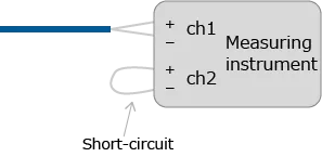
The temperature measurement of a thermocouple is based on the sum of the temperature difference between the two ends of the thermocouple and the temperature of the measuring instrument.
The temperature of the measuring instrument refers to the state where there is no temperature difference between the two ends of the thermocouple. The temperature inside the measuring instrument can be output as a measurement value by short-circuiting the thermocouple with a conductor instead of a thermocouple.
When wired as shown in the figure on the right, ch1 outputs the temperature measured by the thermocouple and ch2 outputs the temperature of the measuring instrument.
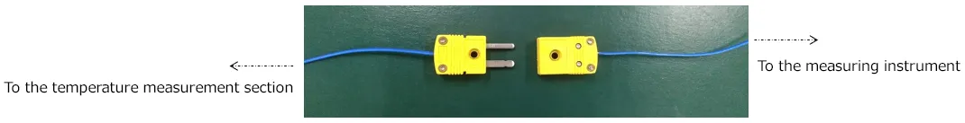
How to Simplify Thermocouple Replacement:Use of Thermocouple Connectors
- Connect the connector for the thermocouple to the terminal block of the measuring instrument
- Connect the thermocouple connected to the measurement object to the connector for the thermocouple
- Easy connection is made possible by inserting and removing the connector on the instrument side and the connector on the measurement object side
Browse “thermocouple connector” to take a look at connectors for thermocouples from various manufacturers.
How to Predict Internal Temperatures when Using Heat-resistant Cases
Heat-resistant cases have the effect of raising the thermal resistance and thermal time constant of the measurement unit.
When using a heat-resistant case in a location where the ambient temperature is higher than the temperature range specified in the specifications of the measurement unit, it becomes important to know how long the case can be used in a high-temperature environment.
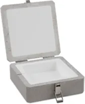
Optional Accessories: Heat-resistant Case
The specifications of heat-resistant cases may show the results of use at an example ambient temperature, but if the temperature conditions are different from those at the time of use, the figures of the results cannot be used as they are.
The parameters related to the temperature of the heat-resistant case are thermal resistance and heat capacity.
If the characteristics of the heat-resistant case do not change due to heat, the temperature difference will change proportionally.
(The characteristics is subject to change if convection conditions, such as wind, change.)
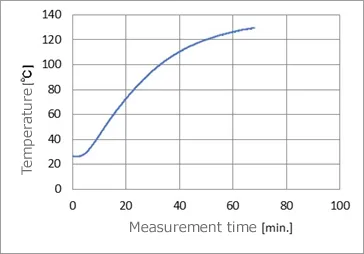
The following calculation shows the predicted internal temperature rise when used in a 200ºC thermostatic chamber using the results of the internal temperature rise when used in a 100ºC thermostatic chamber:
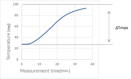
If the initial value of the temperature of the measuring unit is used as a reference and zero point, and the temperature change is ΔT, the maximum temperature difference between the initial value and the temperature in the test chamber will be ΔTmax.
The above graph shows the temperature of the internal thermometer of the measurement unit when the measurement is started in an ambient temperature environment of approximately 27ºC and then put into a temperature test chamber heated to 100ºC.
ΔTmax = 100-27 = 73ºC
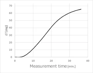
When the temperature of the temperature test chamber is 200ºC,
ΔT’max = 200-27 = 173ºC
The ratio is,
ΔT’max/ΔTmax = 173/73 = 2.37
Since the ΔT after 20 minutes in a 100ºC temperature test chamber is 40ºC, the predicted ΔT’ after 20 minutes in a 200ºC temperature test chamber is multiplied by 2.37, which is approximately 95ºC. Since the initial temperature is 27ºC, the temperature of the measuring unit can be estimated as 122ºC.
The Effect of Water Absorption on the Heat-resistant Case
If the inner part of the heat-resistant case or the measurement unit absorbs water, the characteristics around 100ºC will change.
The temperature rise stops as heat energy is lost to vaporization heat when the water evaporates.
When the water evaporates completely, the temperature rises again.
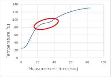
The figure below shows the temperature change when a heat-resistant case is placed in a temperature test chamber at 140ºC.
The WM2000 is placed in the heat-resistant case and the temperature of the terminal block of the WM2000 is measured.
The temperature change becomes gradual once around 90ºC, where the water is evaporating.
The performance of the heat-resistant case rises with water supply to the case. However, when the heat-resistant case is cooled and used immediately, the internal water content is reduced, and no specific temperature change around 90ºC is observed.
The figure below shows the results of the above measurement after cooling the case at room temperature for 2 hours.
The temperature characteristics have changed to a monotonical increase.
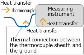
Stabilizing the Temperature of A Thermocouple in A Vacuum
In air, the temperature is stabilized by heat transfer via the surrounding air.
In a vacuum, heat transfer through the air is eliminated, and heat is transferred by radiation/absorption or by contact with a material.
The thermocouple wiring absorbs and conducts the temperature of the tip of the thermocouple to be measured or of an object that comes into contact with the thermocouple when it is being pulled around. Then, the heat stored in the thermocouple heats or cools the terminal block of the measuring instrument.
There are no issues if the temperature of the thermocouple is equal to that of the measuring instrument, however, if a temperature difference occurs, the temperature inside the measuring instrument will not be uniform, causing a measurement error.
Measurement Know-How: Principles of Thermocouple Measurement
The temperature difference between the thermocouple and the measuring instrument can be reduced by forcibly determining the temperature of the thermocouple by placing the thermocouple’s sheath in contact with the housing of the measuring instrument or the ground on which it is installed, immediately before connecting it to the measuring instrument.
When measuring temperatures using thermocouples in a vacuum, it is recommended that the sheath of the thermocouple be thermally connected to the housing of the measuring instrument to reduce temperature differences between the terminal block and the thermometer inside the measuring unit. This way, temperature difference between the thermocouple and the measuring instrument may be prevented.