Processing Thermocouples and Connection to AirLogger™
Cut A7020 (thermocouple) to required length.
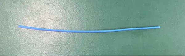
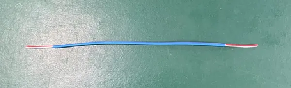
Peel the blue coatings of the cut thermocouple in both ends.
Then, two cables (red and white) appear.
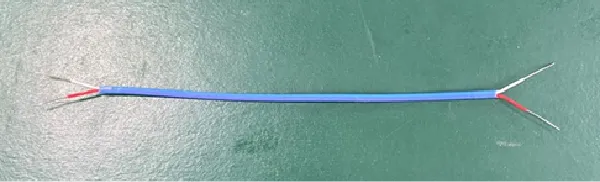
Peel the coatings of two cables (red and white) on both ends.
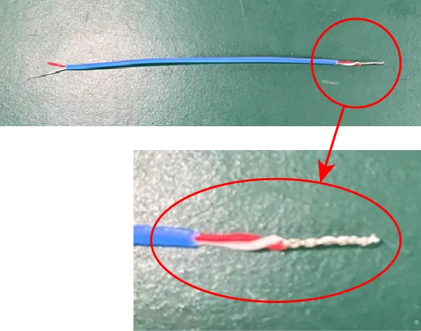
Twist the two core wires in one side (welding them is also applicable), so that they can be turned on electricity.
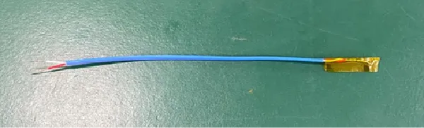
Cover the twisted areas (the contacted area) with tapes, so that the insulation process is done. As such, preparation for the thermocouple is completed.
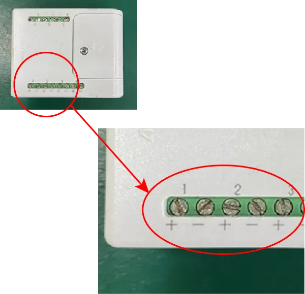
Attach the thermocouple to CH 1 of WM2000TB. Insert the red coating cable to the plus end of CH 1 and the white one to the minus ends of it.
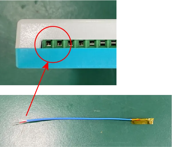
Insert the peeled core wires in these holes.
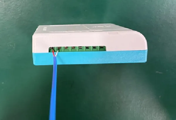
Connection the thermocouple with WM2000TB is completed.