Other Know-How
Measurement of Rotating Objects
When the measurement unit is attached on a rotating object, the electrolyte solution of the battery may become lopsided by the centrifugal force and measurement may not be performed.
Place the measurement unit near the center of rotation, where the measurement unit is less likely to be affected by the centrifugal force.

How to Fix the Units
Screw Fixing
The use of a dedicated case for the unit will enable screw fixation.

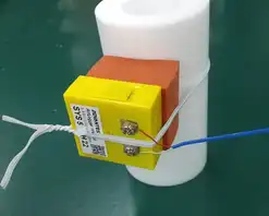
Fixing to a cylinder
Insert a sponge-like cushioning material between the cylinder and the measurement unit, and secure it with a cable tie or wire.
Silicon rubber can be used stably in various environments.

Minimal Fixation
The unit can be secured with a cable tie or wire, while making use of the ditches or projections of the unit.

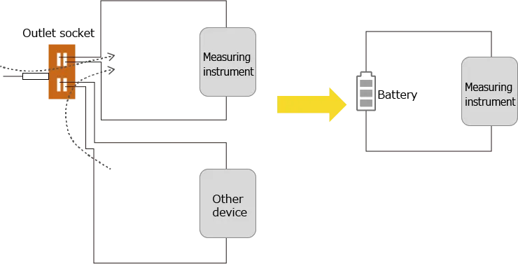
Battery Operation Reduces Tough Power Supply Noise
One of the most difficult noise to remove from measurement results is power supply noise.
Battery operation has less power supply noise and enables low-noise measurements.
Devices driven by an AC power (commercial power source) tend to pick up disturbance noise due to other device connected to the same AC power and the length of the power cable.
Power supply noise may be very large depending on the surrounding environment.
Power supply noise can be classified into common mode noise and normal mode noise. While normal mode noise can be removed by various noise suppression measures, common mode noise is difficult to remove.
When considering noise suppression measures, it is important to prevent common mode noise, which is difficult to remove, from being taken into the measuring instrument.
The user may get free from the difficult task of power supply noise suppression by using battery operation without AC power.
An optional external power supply cable can be used instead of a dedicated battery, but for the same reason, it may make the noise in the measurement results worse than the power supply.
When using an external power supply cable, it may be possible to mitigate noises by using a commercially available USB isolator.
Batch Conversion of the Settings
The setting information of the measurement units can be read and written in one batch process using a file in the AirLogger™ series.
Settings made in the standard software can be saved as a settings file.
Resetting the settings can be easily performed by saving the file with the initial settings.
Note) If the current environment does not match that of the settings file by adding/deleting the measurement units, this causes an error.
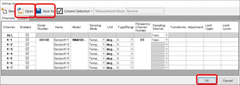
- Open the settings window for the set of measurement units to be set up.
- Enter the settings to be saved.
- By clicking “Save As”, create a file and save the current settings.
- Load the settings file to be used with “Open” and rewrite the settings in the settings window.
- Press “OK” to put the settings above into effect.
Current Measurement
There are two main approaches of measuring current:
- By the voltage generated with inserting a micro resistor
- By the voltage corresponding to the magnetic field extracted from the current
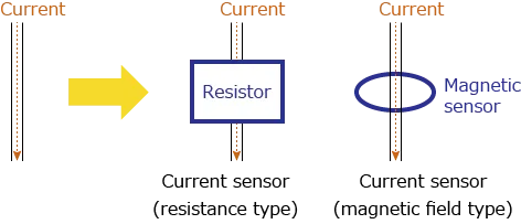
Approach 1: Inserting A Micro Resistor
The relationship between current, resistance, and voltage can be obtained by Ohm’s law as follows:
Current = Voltage/Resistance
The current can be measured by inserting a resistor of known value and measuring the voltage drops.
● 250 Ohm shunt resistor
The shunt resistor can take a large value since the current output sensor is a current source output.
By using a 250 Ohm shunt resistor, the output can be converted from 4 to 20 mA to a voltage of 1 to 5 V.
The relationship between shunt resistance and voltage is as shown in the above equation, therefore, halving the resistance value shall also halve the output voltage.
Current can be measured by entering an arbitrary resistance value into the conversion formula.
Example) In the case of 100 Ohm
If x/100 is input to the conversion formula, current value 4 to 20 mA can be measured with 0.4 V to 2 V, and the converted current value is output. (Unit: A)
Approach 2: From Magnetic Fields
When a current flows through a wiring, a magnetic field is generated in the surrounding area. From the magnetic field generated, the current can be measured according to Ampere’s law.
Some current sensors output the current value as a voltage, and the current value can be measured by this voltage.
Since it will be a magnetic field extraction, this approach is suitable for measuring AC currents and currents of 1 A or more.

Checking Logs on a Remote PC During Measurement
Reading log files of measurement results and displaying them graphically are possible with the AirLogger™ standard software.
This function can be applied to create or copy log files to a shared folder on the network, allowing different PCs on the network to view the measurement results.
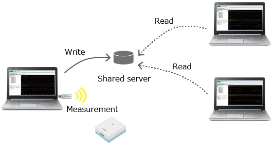
Displaying results via the network is also possible for data during measurement.
(Note: Please beware of network problems caused by access to files.)