Acceleration and Vibration Measurement
 Acceleration
 Strain
Outline of the Sensor (Strain Type Acceleration Sensors)
Fix an acceleration/vibration sensor so that it will not come off or be loose at the connection.
Since acceleration/vibration measurement involves measuring moving objects, fix the sensor so that the measurement results are not affected by movement of the sensor cable.
Check the orientation before installation since sensors have directions of “X, Y, and Z”.
The strain converter type acceleration sensor needs no external power supply and is driven by the bridge input of the strain logger.

vibration sensor (1 axis)
Installation
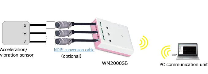
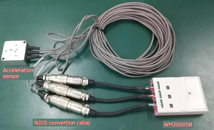
Connect the data logger to the acceleration/vibration sensor.
When the sensor for the NDIS connecter is used, it can be attached easily by using the optional NDIS conversion connector.
Setting for collecting data
- Activate the standard software of WM2000.
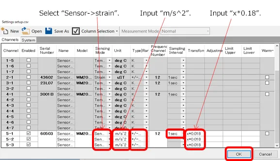
- Click on “Settings” -> “Setup…” and open the window for setting.
- Change “Sensing Mode” to “Sensor -> strain”.
- Input units in “Unit” (for example m/s^2)
- Set range based on the strain and voltage applied to the Data logger with “Type|Range”.
When range set is larger than the largest range of the sensor, measurement is done steadily. - Select a sampling interval by “Sampling Interval”
The sampling intervals can be specified per measurement unit. - Input an equation to convert strain and output voltage specified by the sensor to acceleration/ vibration at “Transformation”.
Example:If the conversion formula for ±20 G at 0.5m V/V rating is acceleration [m/s^2] = (strain [μ]) × 0.18, input “x*0.18”. - Click on “OK” button to finish the setting.
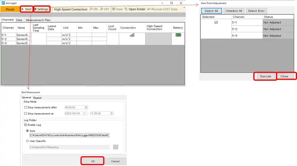
Execute Measurement
- Click on “Settings” -> “Zero Point Adjustment” button to pop out the window for 0 adjustment.
- Insert check marks to channels connected to the acceleration sensor, click on the “Execute” button to execute the 0 adjustment.
- Status is changed from Not Adjusted (grey color) to Adjusted (green color).
- Click on “Close” button to finish the 0 adjustment.
- Click on “start” button to pop out the “Start Measurement” window to input measurement conditions.
- Click on “OK” button of “Start Measurement” in measurement conditions input window to start measurement.
- “Start” is changed to “stop”. Click on “stop” button when measurement is finished.
- Close the recovery window when recovery (re-transmission of lost) of all units is completed.
* The recovery window will not appear if the measurement is executed without logging.
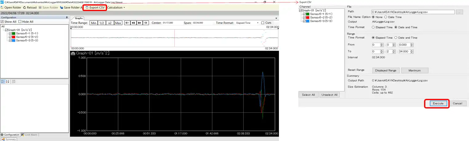
Viewing Measurement Results and Outputting the Results
- Click on “view” button to pop out the view window and view measurement results.
- Click on “csv” button to pop out the window for setting CSV.
- Click on “Execute” button.