Communication Environment Know-How
Data Storage Capacity of the Internal Memory
The number of data that can be stored in the internal memory of the measuring unit in case of communication failure is as follows:
| WM1000 | Max. 10 sampling |
|---|---|
| WM2000TA | 16000 |
| WM2000SA | 32000 |
| WM2000TB | 7100 |
| WM2000SB | 12000 (100 ms sampling or more) |
| (Undefined) (*50 ms sampling or less) |
* When sampling is 50 ms or less with WM2000SB, all data within 26 hours are stored in the internal memory regardless of the sampling period.
Measurement in A Poor Communication Environment – Offline Mode
When wireless data loggers are used in locations with poor communication conditions, wireless communication is repeated to ensure synchronization and retransmission of data.
Using in locations with poor communication conditions further degrades the radio wave environment and increases power consumption.
If AirLogger™ is unable to communicate for a certain period of time, the operating mode switches* so as to continue measurement efficiently.
* Long-term monitoring mode does not switch to offline mode.
If communication is lost for more than 1 minute during measurement, the measurement unit goes into offline mode.
In offline mode, wireless communication is not available and the measurement unit continues to measure asynchronously.
Measurement stops when a signal to stop measurement is received from the PC communication unit* or when the internal memory for backup is full.
* Apart from the stop button, if the Lost data recovery function is executed, the PC communication unit will send a stop measurement signal to the measurement unit as a pre-processing step.
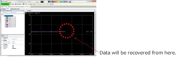
Data measured in offline mode may be recovered by the PC communication unit using the normal “Lost Data Recovery” function.
During offline mode, the communication environment between the measurement unit and the PC communications unit is likely to be poor.
Change the location of the PC communication unit or use in an environment with a good communication environment to recover the data.
If “LOST Data Recovery” is not accepted, reset the status of the measurement unit by selecting Settings -> [Force reset of all sensor units…] and then execute “LOST Data Recovery” to recover the data.
Caution
“LOST Data Recovery” must be performed with the measurement data displayed.
Data cannot be recovered if the data displayed on the standard software is reset by restarting the standard software, sending the settings again via [Setup…], or starting the next measurement.
How to Use the Offline Mode
What To Do If the Measurement Unit Becomes Uncontrollable
If the measurement unit becomes uncontrollable for some reason, such as if it becomes completely out of synchronization or if the measurement stop signal is not received, forced reset [Force reset of all sensor units…] will enable control of the measurement unit.
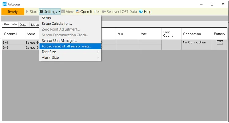
Forced reset is performed on all units registered in the PC communication unit.
If the forced reset succeeds, the settings must be sent back in order to process the measurement once again.
Even after a forced reset is executed, the standard software still displays the latest measurement results, so the LOST data in the memory inside the measurement unit can be recovered.
Recovery of LOST Data During Measurement
(WM2000 Series Long-term Monitoring Mode)
*Long-term monitoring mode is a function available with Standard Software Rev. 2.02.00, PC Communication Unit Rev. 2.2.1, and Measurement Unit Rev. 2.2.1 or higher.
For more information, please refer to “Usage Handbook: Confirmation of Revision for Software and Unit”.
The WM2000 series has an extensive memory function allowing data, which could not be communicated, to be stored in the memory.
For more information, please refer to “Measurement Know-How: Data Storage Capacity of the Internal Memory”.
In normal mode, if communication with the PC communication unit is lost for a long period of time due to real-time property or low power consumption, data is recovered from the measurement unit with “Recover LOST Data” after the measurement is completed. Since the data is recovered after measurement, the results may not be checked from the log data during measurement before retrieval.
In long-term monitoring mode, LOST data is retransmitted in the order of oldest to latest during measurement.
When the internal memory of the measurement unit becomes full, the oldest data will be overwritten sequentially.
(In normal mode, measurement stops when the internal memory is full.)
Owing to the allocation of transmission time, the smaller the number of channels in the measurement unit, the faster the retransmission.
If the communication environment is poor and retransmission occurs frequently, select a measurement unit with a smaller number of channels.
(Note that this depends on the maximum number of channels of the unit, not on the active number of channels.)
For more information, please refer to “Usage Handbook: How to Use Long-term Monitoring Mode”.
Interference
Interference comes in two types:
- The inability to communicate due to disturbance waves by non-intended communication.
- Receival of a non-intended communication due to another communication being mixed up.
In the case of analog radios, communication contents may be rewritten due to interference.
In the case of digital radios, communication may be lost due to interference, but generally the contents are not rewritten.
If communication is lost, communication can be ensured by retransmitting the data.
Current wireless communications generally use digital communications.
AirLogger™ uses digital communications.
When interfered, radio waves are received but communication is not possible, which shows no difference from the normal state when a radio wave strength check is performed.
When there are frequent reception errors even if the radio wave strength check is normal, there is a high possibility that the environment has a lot of disturbance radio waves.
For instance, in 2. 4GHz band communications, multiple frequency channels are set for each standard. Even if the same 2.4 GHz band communication equipment is used, there would be no interference if different frequency channels are used.
Even in the case of using the same frequency channel, if the radio wave to be communicated is strong, interference is less likely to cause problems. Likewise, the stronger the disturbance wave is, the more likely it is that communication will be lost.
* If multiple PC communication units use the same frequency channel in WM1000, the PC communication units that can be connected will be indefinite.
Visible Ease of Signal Connectivity
The typical transmission power of wireless communication ICs in the 2.4 GHz band is approximately 0 dBm (1 mW), while the minimum received power is approximately -90 dBm (1 pW), which is a difference of 10 to the ninth power.
If a transmitter is placed on a steel tower with a good vantage point, reception may be possible even at a distance of 1 km, but in a typical indoor environment, it is often difficult to connect even at a distance of approximately 10 m.
On the other hand, a receiver placed on the backside of a car in a space with a good vantage point may not be able to communicate, while in an indoor test room it may communicate at the same distance.
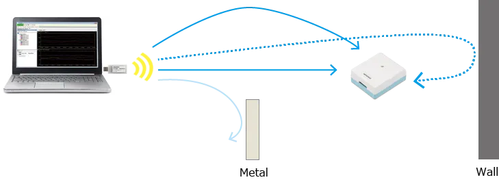
When radio waves hit an object, they are transmitted, reflected, diffracted, or scattered and bent in all directions.
Metals are hard to transmit and easy to reflect, while resins are objects that are easy to transmit and hard to reflect.
Radio waves that follow different paths can be strengthened or weakened at different locations by bending.
This is called “multipath fading”.
Since the difference between the transmission power and the minimum received power is large, even weak scattered waves may be received.
Indoor locations are advantageous for close communications since multiple propagation paths between the transmitter and receiver can be secured, while outdoor locations are advantageous for distant communications as there is less attenuation.
If the receiver is visible from the transmitter, it becomes easier to connect since a direct propagation path will be secured.
If the receiver is not visible from the transmitter because it is blocked by a metal object, it may be easier to connect if a metal object is placed on the opposite side to reflect the radio waves.
Review of the attachment method
-
When attaching the PC communication unit and measurement units, be sure to attach them in positions where the measurement units are visible from the PC communication unit.
In addition, if the PC communication unit is placed close to the floor, radio waves coming out of the PC communication unit are absorbed by the floor, so place the PC communication unit at as high a position as possible.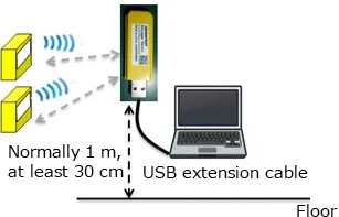
-
Do not use metal tape such as aluminum tape to attach the temperature measurement unit.
The metal tape will block radio waves.
We recommend using resin tape, double-sided tape, or cable ties for attachment under normal conditions, and polyimide tape or silicon tape under high temperatures.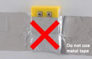
Effective use of a USB extension cable
If there is a metal or concrete wall between the receiver and transmitter, it will obstruct radio waves and hinder communication.
Attach the PC communication unit at a position where it is visible from the measurement units, such as near a window, by using USB extension cable.
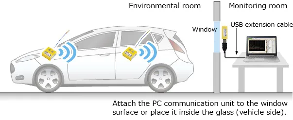
* If a USB extension cable is used for the connection between the PC communication unit and PC, use a cable of 3 m or less in Europe, as stipulated under the Radio Law.
Improvement of the radio environment using a passive antenna
What is a Passive Repeater?
A passive repeater is a product in which two 2.4 GHz antenna are connected by a coaxial cable. It does not use an amplifier, so no power supply is required.
When the radio environment deteriorates due to metals or other obstacles, the radio environment may be improved by placing a passive repeater between the temperature measurement unit and PC communication unit.
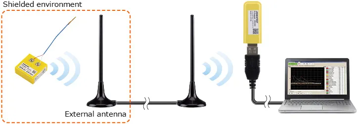
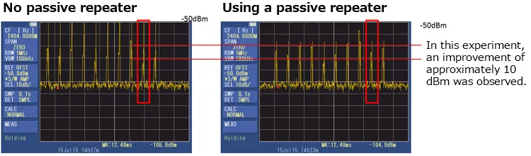
Experiment example: Signal strength measurement using a spectrum analyzer
Improvement of the radio environment using the passive attachment
(Option for WM1000 only)
What is the passive attachment?
The passive attachment consists of antennas, dividers, and the PC communication fixing package.
By bringing the internal antenna of the PC communication unit and the antenna of the passive attachment closer together, the signal strength improvement effect of the attachment can be maximized.
In addition, signal strength can be improved by attaching a passive relay antenna near the temperature measurement unit experiencing radio wave interference.
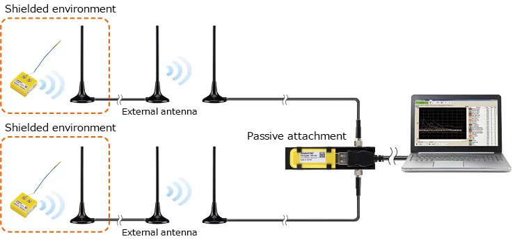
The attachment ports of the dividers are SMA-J connectors; attach the antennas using coaxial cables with SMA-P connectors.
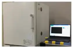
Wireless Communication in Metal-enclosed and Shielded Spaces
Radio waves do not transmit through metal, but are reflected.
Radio waves do not pass inside or outside in a shielded space, but they often do in a metal-enclosed space.
Whether radio waves are able to go out from inside a metal box, such as a thermostatic chamber, becomes an important issue.
Thermostatic chambers, such as the one pictured at right, may often receive radio waves if a receiver is placed near the device.
If the device has a window, placing the receiver near the window will give even stronger reception.
On the other hand, reception becomes more difficult in a test chamber surrounded by wire mesh.
Radio waves are emitted through the gaps where metals overlap, but if the metals are electrically connected, it is more difficult for radio waves to be emitted through the gaps.
If an empty can, usually filled with sweets or candy, is covered with a lid, radio waves will nonetheless be emitted since the surface is insulated, however, if the can is grinded to make both sides conductive, radio waves will not be emitted.
Radio waves will not be able to pass through holes in the wire mesh, if the holes are sufficiently smaller than the wavelength. The wire mesh is secured with screws so that everything is conductive allowing the shielding effect to be high.
Connecting the PC communication unit to a PC using a USB extension cable makes it easier to install the PC communication unit in a location where it can be easily connected.
Transit Measurement of Communication Area using WM1000
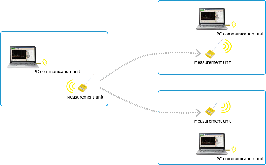
In WM1000, pairing PC communication unit with the measurement unit is done by system number and channel number, not by individual serial identification.
This means operating measurement units with the same system number and the same channel number in the same measurement space will not work properly.
On the contrary, if multiple PC communication units set with the same system number are installed in different spaces away from each other and the measurement unit is moved, the measurement results are sent to the nearest PC communication unit. (Each PC communication unit is set to be in measurement mode by the standard software.)
Caution
If the measurement unit is outside the communication range of all PC communication units, the measurement unit stops measurement and enters a mode to search for a communication destination, draining battery more than during the measurement.
It is recommended to turn off the switch if the measurement unit is out of the communication range for a long period of time.
If the communication range of PC communication units overlap, operation becomes unstable.
Avoid collecting data where communication areas overlap.